Privacy statement: Your privacy is very important to Us. Our company promises not to disclose your personal information to any external company with out your explicit permission.
Third, DK7725E CNC wire cutting machine
Symptom: The pulse power supply output is faulty.
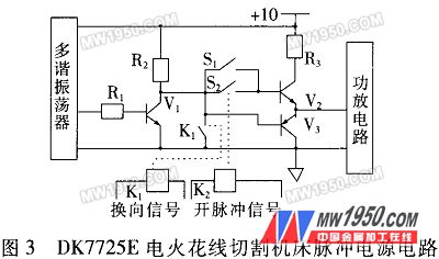
The machine tool generates a corresponding pulse width and interval by the multi-vibrator, and is inverted and amplified by the transistor V1. When the control machine sends a pulse power signal, the relay K2 is sucked, and the pulse waveform signal is transmitted to the power amplifier circuit through the emitter output device V2. For machine tool discharge machining. S1 is the debugging switch. When the control machine has no pulse signal, press S1 to force the output pulse power. When the wire motor is reversed, the relay K1 is pulled in, and the transistor V3 is turned on to turn off the pulse power signal. The pulse power supply circuit is shown in Figure 3.

The main fault of the pulsed power supply output is that the output current is too large, usually because the power amplifier tube is broken down. The short-circuit current of the normal pulse power supply is 0.6~0.8A for each power amplifier tube, and it is broken down when it is greater than 3A. The reason for the success of the discharge tube breakdown is that the next stage power amplifier tube fails; if the pulse power switch on the control machine is turned on, there is no output after pressing the cutting key, which is caused by the collector of V1 and the base of V2 are not connected. At this time, it can measure whether there is 6V voltage across the coil of relay K2. If there is any indication, the relay is damaged. If it is not, then the controller does not send a pulse signal. The interface circuit of the control machine should be checked. In addition, if the pulse motor output is not cut off when the wire motor is commutated, it is usually caused by the failure of the relay K1. In this case, the relay should be replaced.
Fourth, DK7725E CNC wire cutting machine
Fault phenomenon: X-axis working jitter, accompanied by mechanical noise.
The machine tool is controlled by a TP801 single board machine, and the servo drive part uses a stepping motor. First, the X-axis motor is disconnected from its mechanical part. If the fault persists, it indicates that the fault source is in the electrical part. The circuits related to the fault are a computer host circuit, an interface circuit, and a step drive circuit. When the "switching method" is used to drive the X-axis motor with the Y-axis drive circuit, the X-axis fault is eliminated; the X-axis drive circuit drives the Y-axis motor, and the fault occurs on the Y-axis. It is thus judged that the X-axis drive circuit has failed. Inspection found that the X-axis drive circuit of a high-power transistor 3DD 101B is open, causing the stepper motor input phase loss operation. After replacing a new tube, troubleshoot.
In economical CNC machine tools, the high-power transistor failure rate of the step-drive circuit is higher because of the open-loop control of the system. During the machining process of the machine, if the overload or overcurrent occurs for some reason, the open loop system cannot detect and stop the circuit, which will inevitably burn the transistor.
Five, DK7725E CNC EDM wire cutting machine
Symptom: The Y-axis is out of step in fast machining.
The servo drive part of the machine uses a stepping motor. For the TP801 single board machine, the stepping motor's out of step is mainly the PIO signal failure or the interface circuit fault between the single board machine and the stepping drive circuit; if it is connected in series to indicate that the stepping motor is turned on and off each phase. This fault can also occur when the LED or stepper drive circuit is damaged.
Check the LEDs first. Because the Y-axis of the A, B, and C three-phase indicators are illuminated during the processing, the diode itself has no fault, but one phase has a slight lack of illumination, indicating that the phase is faulty. Check the dynamic driving signal of the LED connected to the stepping drive circuit, and the signal at the end is significantly different from the other ends. Replace the chip on the machine with a good PIO chip and the fault still exists. According to the working principle of the system, the fault source should be in the interface circuit. The interface circuit of the system Y axis is shown in Figure 4.

Static check the interface circuit components are not faulty. Power-on dynamic check, the input signal is balanced in three phases and the output signal of the 1V23 switch tube 3DK4B is different from the other two phases, indicating that the performance of the 1V23 switch tube is deteriorated, resulting in unbalanced voltages of the A, B, and C phases, resulting in the Y-axis. The motor loses speed when it is fast.
Troubleshoot after replacing a new switch tube 3DK4B.
| Previous page | 1 | 2 | 3 | Next page |
November 18, 2024
November 11, 2024
Bu tedarikçi için e-posta
November 18, 2024
November 11, 2024

Privacy statement: Your privacy is very important to Us. Our company promises not to disclose your personal information to any external company with out your explicit permission.

Fill in more information so that we can get in touch with you faster
Privacy statement: Your privacy is very important to Us. Our company promises not to disclose your personal information to any external company with out your explicit permission.